Resistor Flex part 2
How to use computers to build devices!
2025-03-25
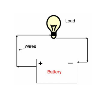
What makes an electric circuit?
- Voltage → Volts (V)
- Current → Amps (A)
- Resistance → Ohms (Ω)
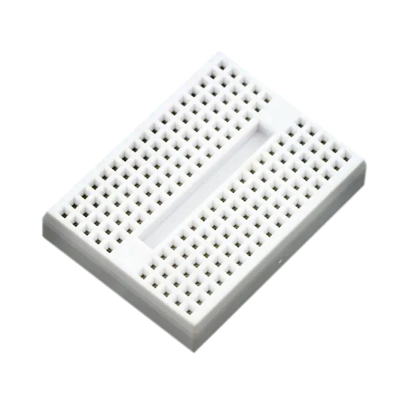
Breadboards make testing complicated circuits easy!
Transistors: Electrical switches
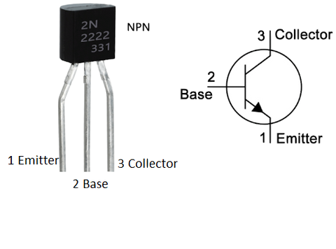
OFF if no current delivered to the Base
ON when even a tiny bit of current flows to the Base
Hands on challenge: Night light
Components:
- Breadboard
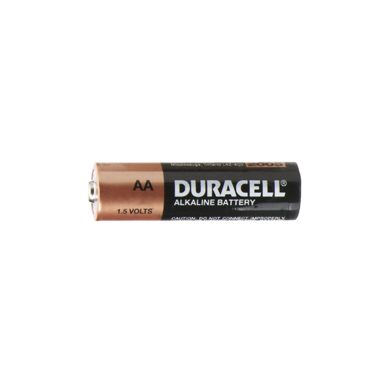
- 5 V power supply →
![]()
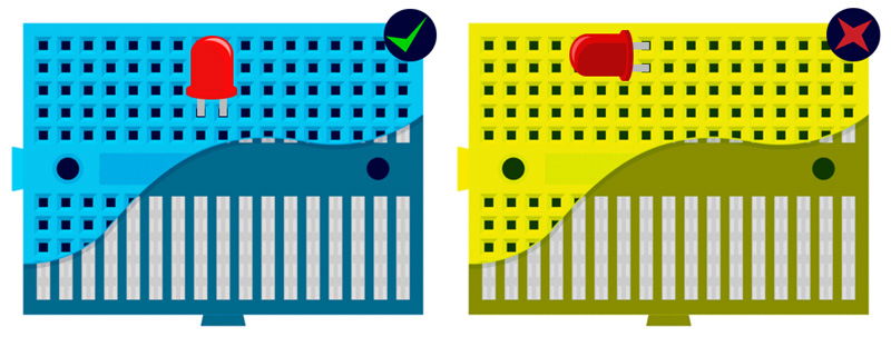
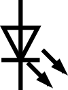
- LED →
![]()
- 220 Ω Resistor →
![]()
- 100 kΩ Resistor →
![]()
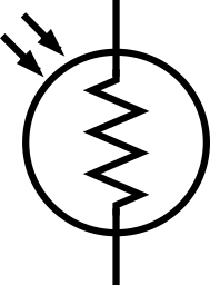
- LDR →
![]()
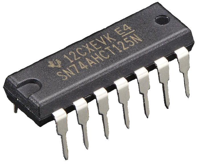
- Transistor →
![]()
- Jumper cables


The main components of the mushroom lamp
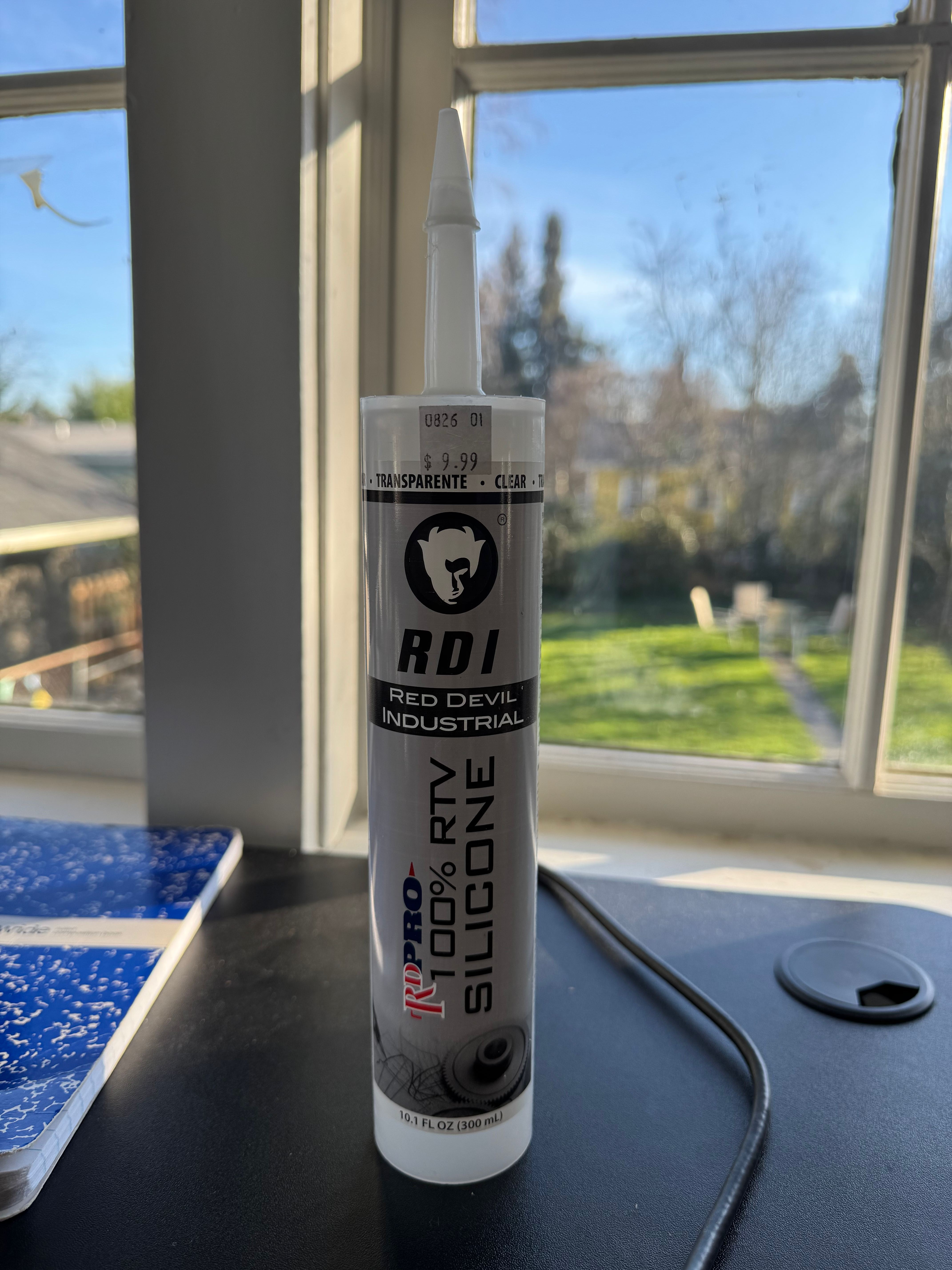
- A piece of bark
- Silicone sealant
- Red-Green-Blue LEDs
- An ESP-32 microcontroller (a small computer)
- A level shifter and some resistors to control the LEDs
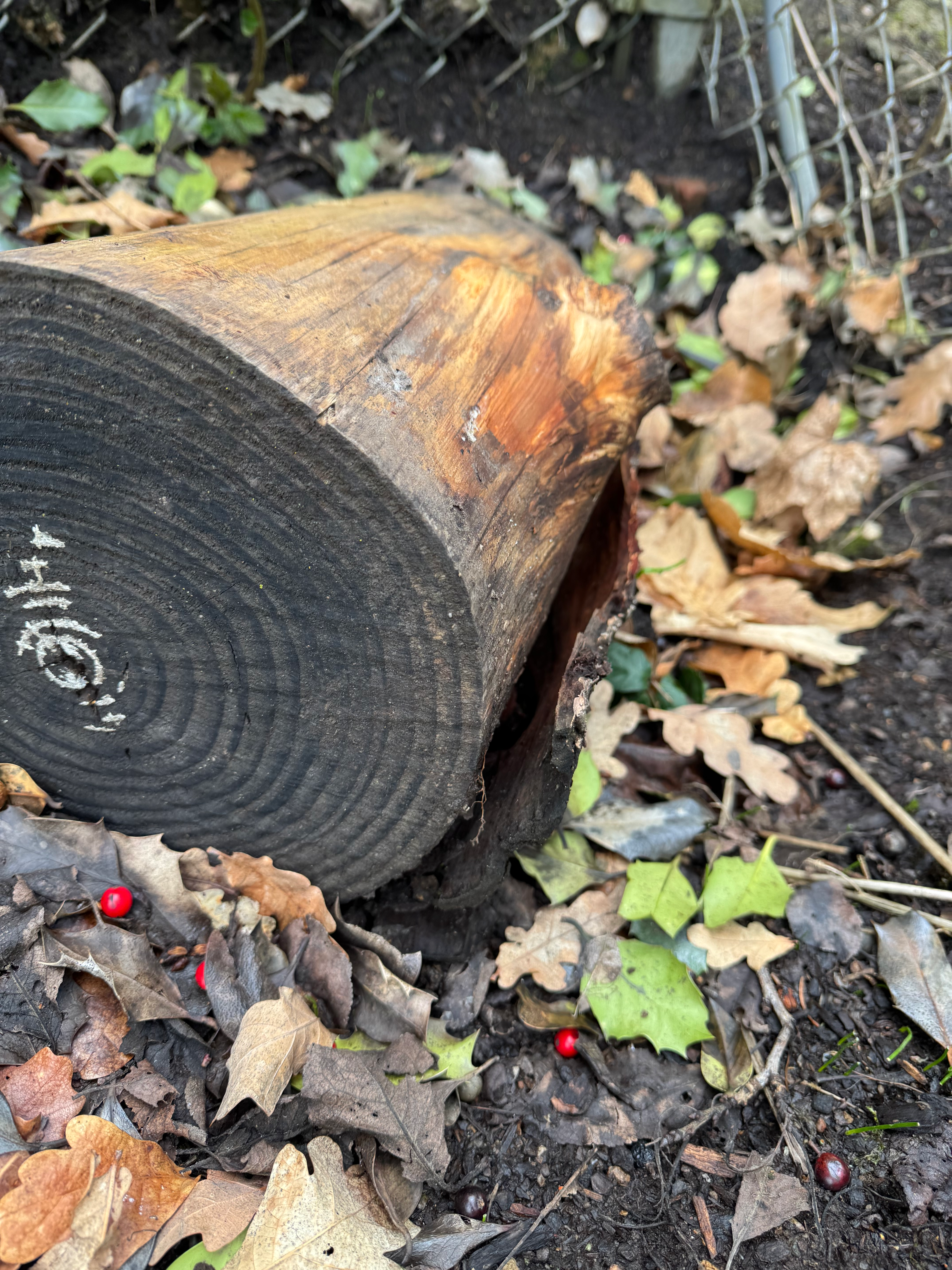
![]()
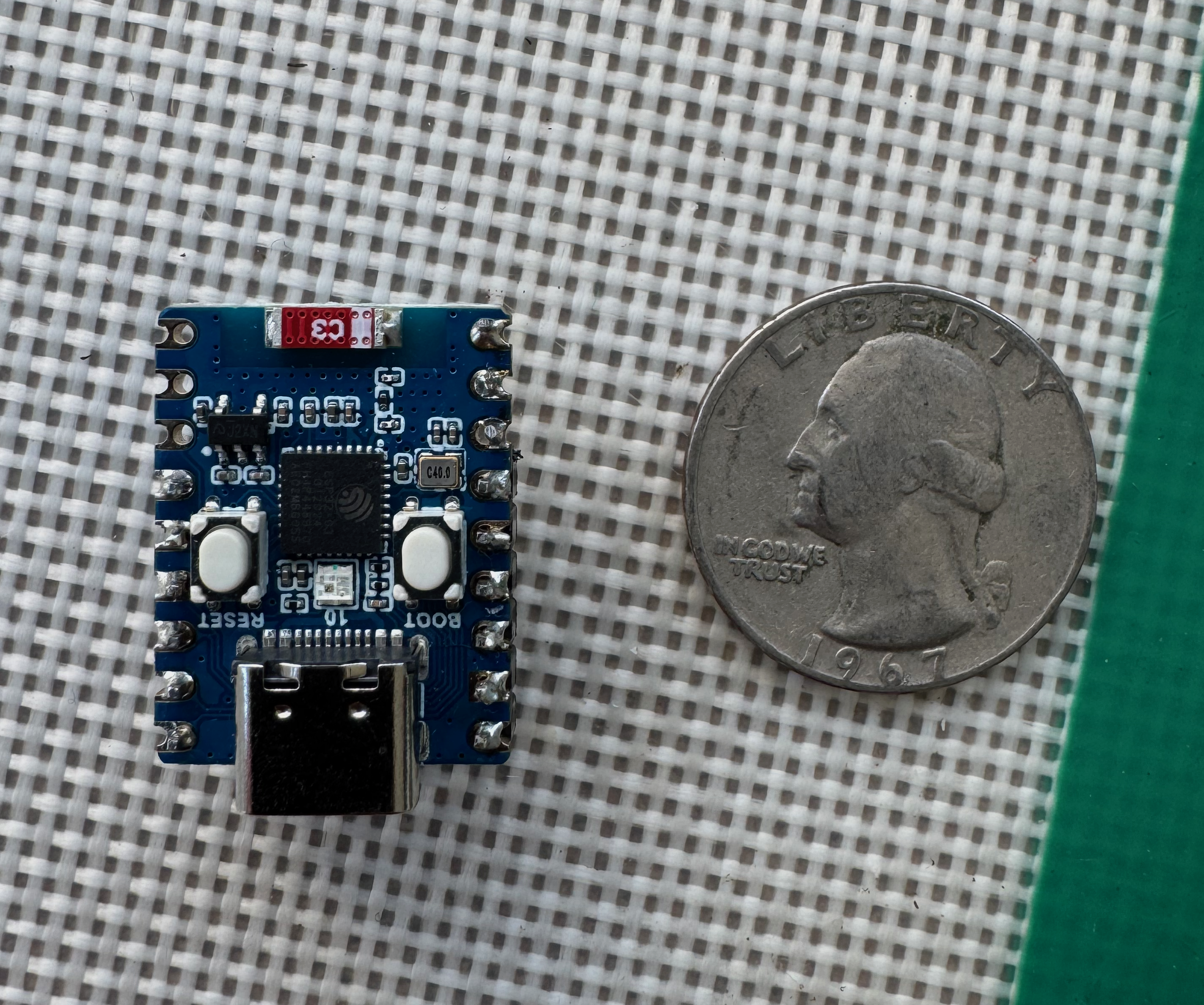
You can use a computer to control a circuit