Mushroom Lamp v1
Overview
I was inspired by this video by DIY Perks on using silicone caulk to craft mushrooms with embedded LEDs – but I recently got myself an ESP32-C3 super mini dev board, and I wanted to see if I could get it to control the lights to display some kind of pattern!
While the physical structure of the lamp is complete, I’m still working on incorporating an MQTT connection to HomeAssistant – that way I can cycle through different light patterns from a dashboard!
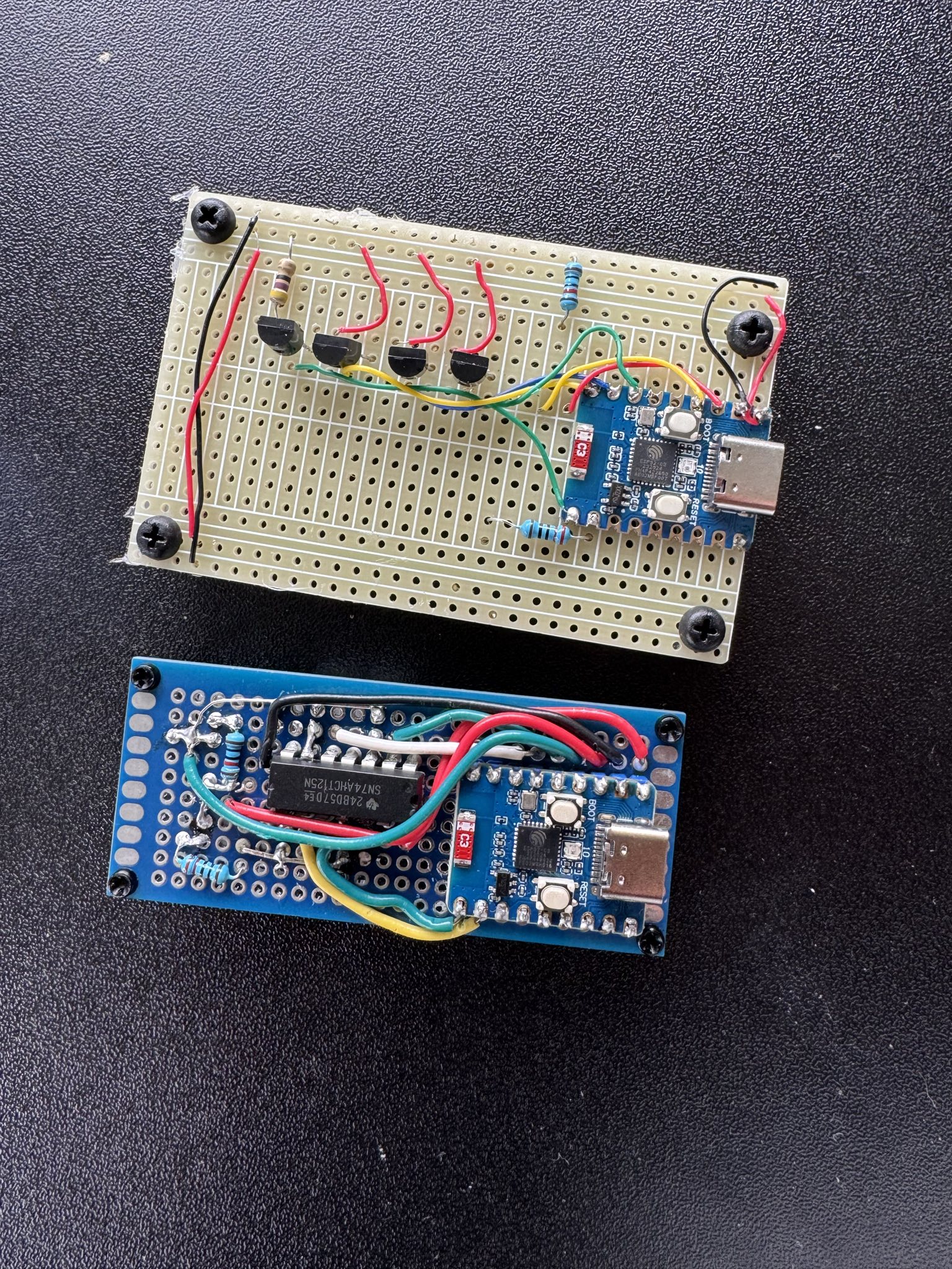
March 2025 Update: I started noticing that some of my connections seemed to be shorting out – this was after all my introduction to soldering. I decided to rip the control board out and start from scratch with some better design planning and some nicer connectors to plug each mushroom into the board. See below for a little side-by-side of my first board and this new board!
August 2025 Update: I recently learned a lot more about ESPhome and was able to totally rework the script so that the lamp is controllable in Home Assistant, with a slider bar to regulate the output brightness! The mushrooms are also now “breathing” in a sine pattern, better fitting how real breathing patterns look.
Materials & Components
- A piece of bark (found in my back yard)
- Silicone caulk sealant
- Silicone dye
- Standard LEDs (1x red, 1x green, 1x blue - and a bonus white flickering one taken from an LED candle)
- A flexible strand LED
- An ESP32c3 supermini microcontroller
- NPN2222a transistors (to convert the 3.3 V GPIO output to 5 V)
- In my re-done board, I used a 74AHCT125 - Quad Level-Shifter instead of 2222s
- A light-dependent resistor (LDR)
- A 10 kΩ pull-up resistor for the LDR
- 470 Ω resistors (for the LEDs)
Assembly
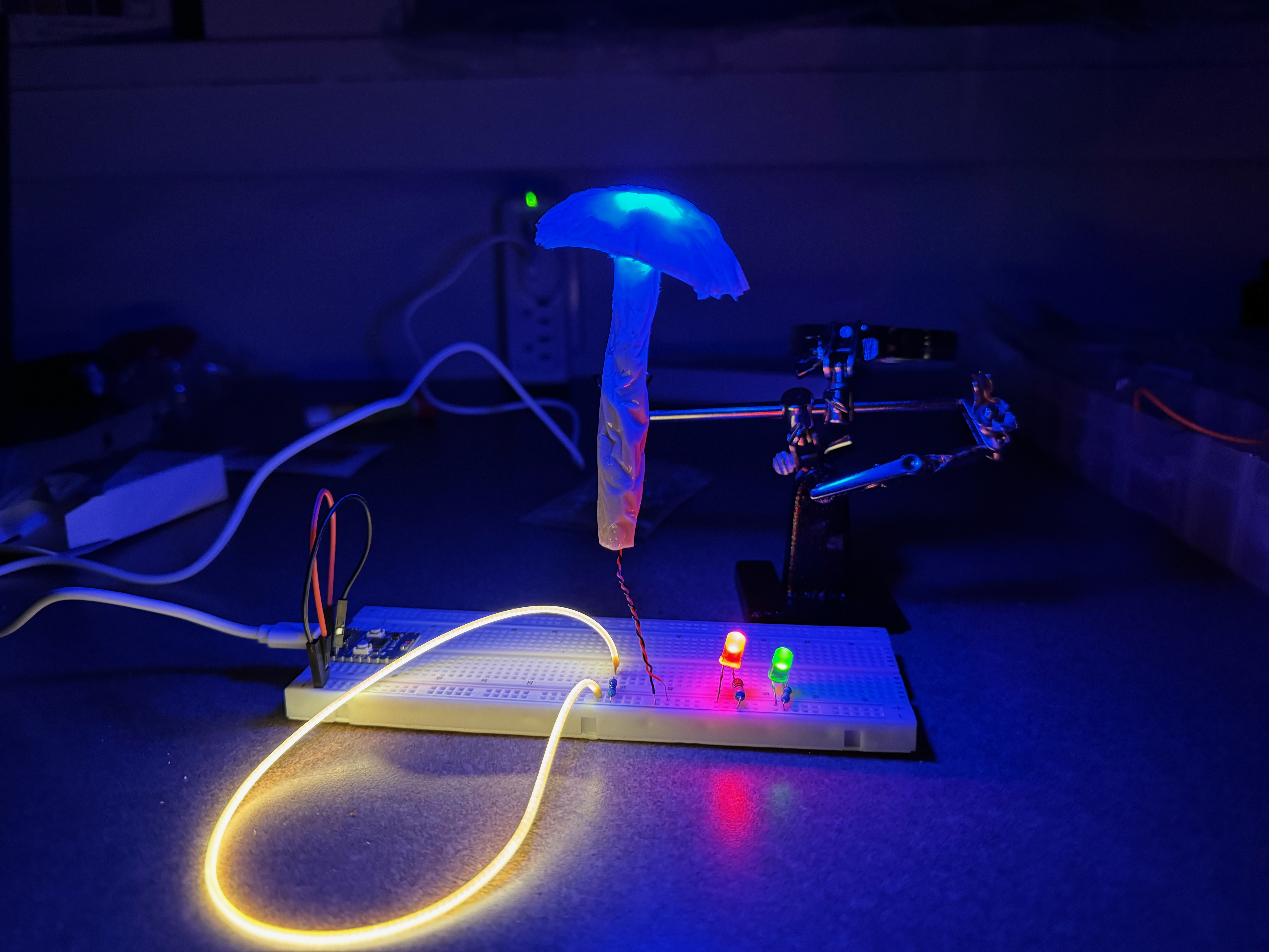
Next, I soldered the LEDs to power lines – I decided to directly integrate the current limiting resistor into the stalk of the mushroom so I wouldn’t be tempted to test the mushrooms without a resistor (a stupid mistake that killed my first test mushroom!).
I then crafted the mushroom stalks using the silicone caulk: I squirted a line of some caulk out onto some plastic film, added a small amount of dye to make nice colors, and squashed the LEDs into the line. By folding the plastic wrap over and kneading carefully, I got the wires embedded in the center of the caulk and a mostly round cross-section.
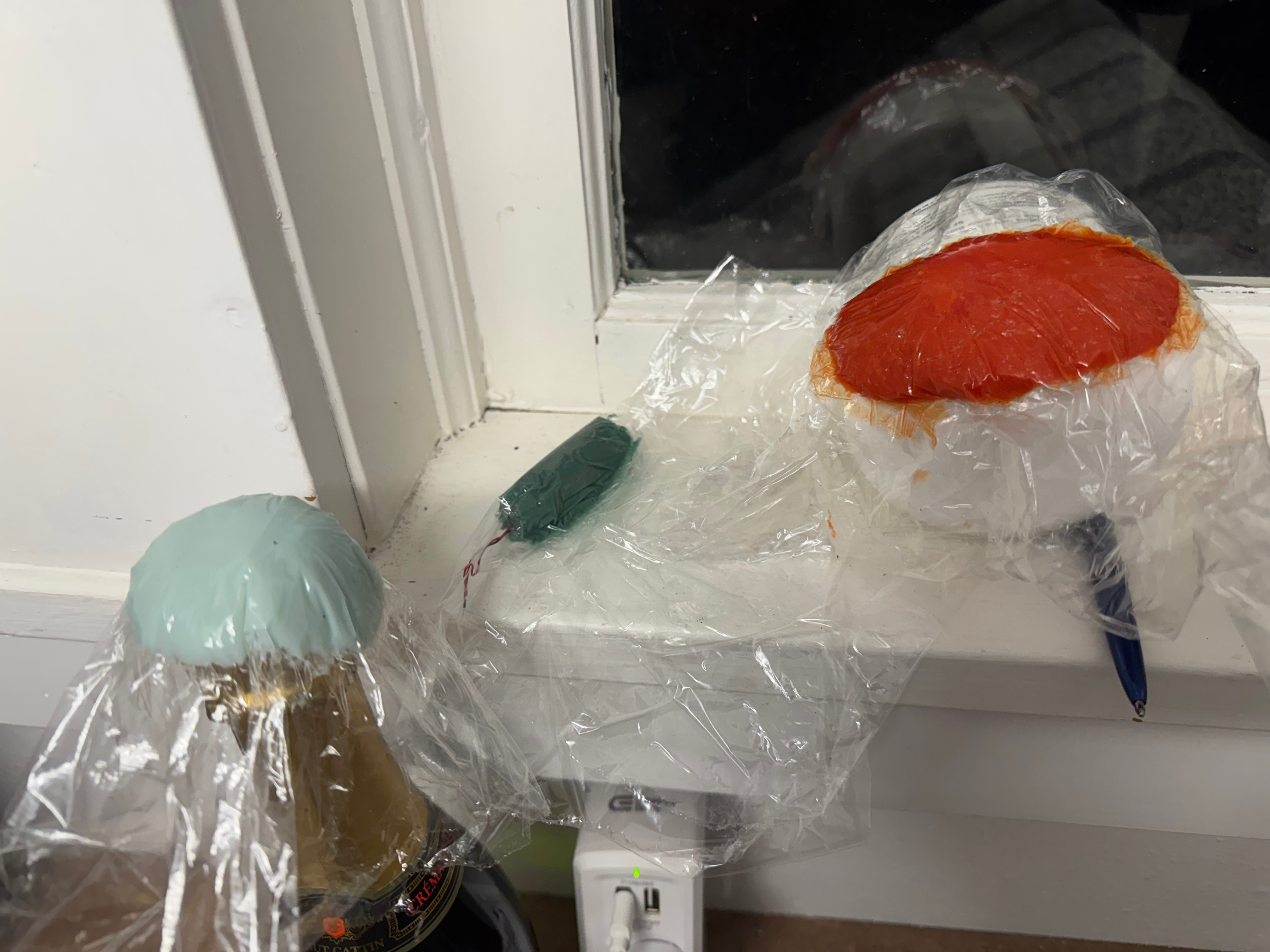
For the mushroom caps, I squeezed out more caulk and dye to match the LED colors and left them to dry between layers of plastic wrap. I used the tops of bottles and curved things to help them set in the right shape. Once everything dried, I used a big glob of caulk to glue the tops to the bottoms.
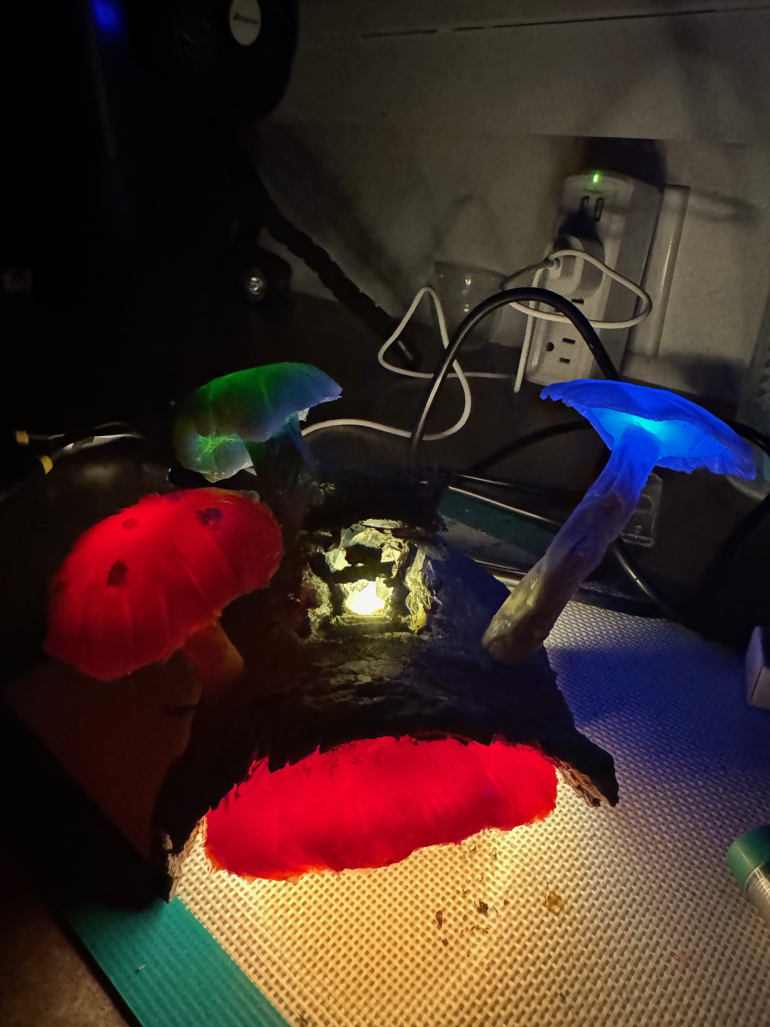
I then drilled 10 mm holes into my log in what I thought would appear to be a natural arrangement and fed the trailing LED leads through and then used more caulk to glue them in place. I also drilled and glued in place the light-dependent resistor near the back of the bark and the bare flickering LED right in the center. I left the underside of the amanita off for the time being – my vision was to make it big enough to cover the board underneath, so it needed to be glued in place as a final step.
Next I started work on soldering the PCB. The main components here are the ESP32-C3 itself, one NPN2222a transistor for each LED (discussed a little more below), a pull-up resistor for the LDR, and trailing wires to power each LED pointing up away from the board so that they’d be long enough to solder to the trailing wires of the glued-in LEDs (This turned out to be a huge pain).
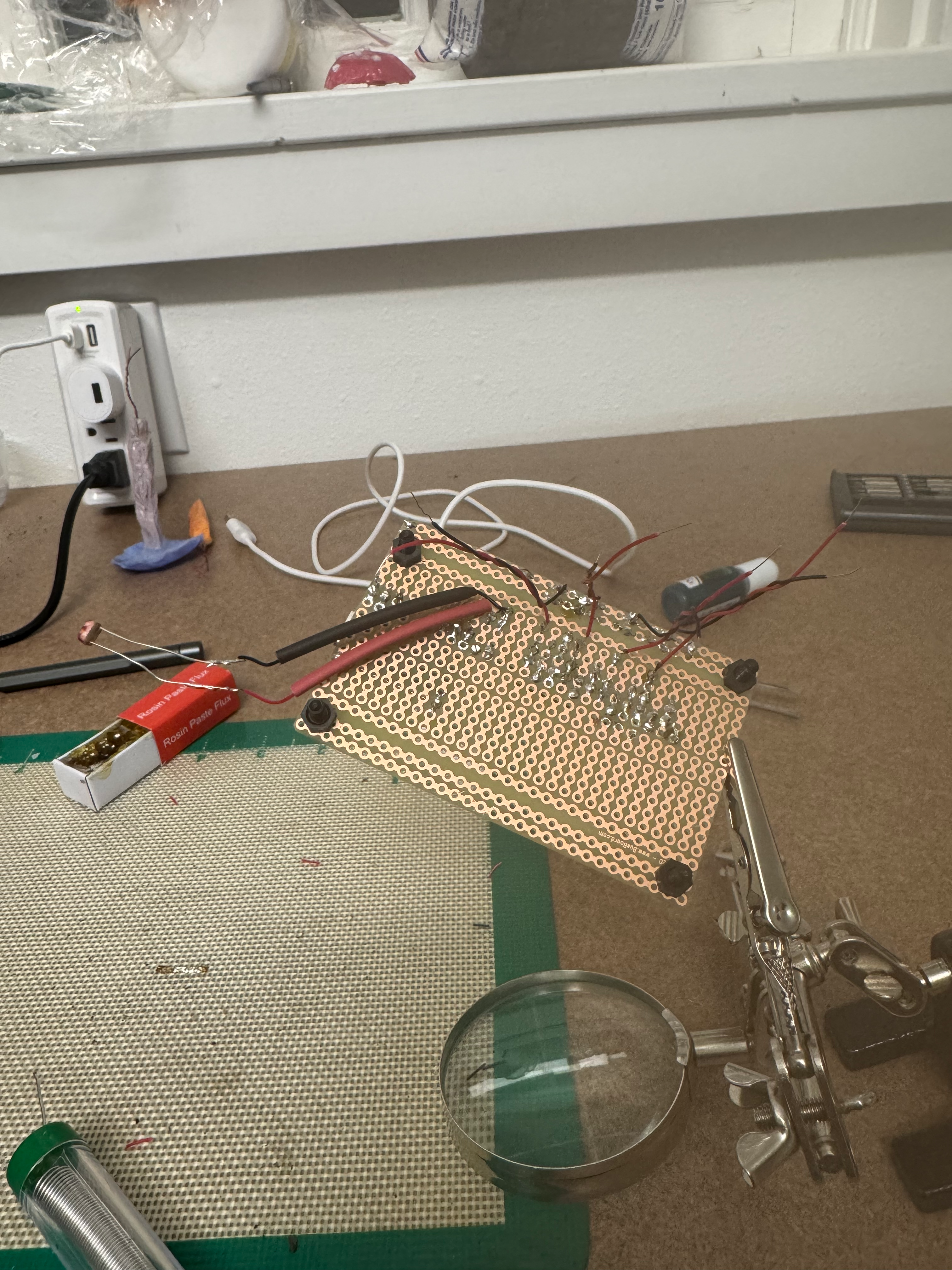
The NPN2222a transistors were my rudimentary attempt at performing level shifting. The GPIO data out voltage is 3.3 V – and in my testing, it made the LEDs just not quite as bright as I wanted them, even after messing around with different resistor levels. I decided to bump them up to 5 V by connecting the Vcc lead to the emitter pin of the transistor, and the GPIO data line connected to the base. This allowed the ESP32 to regulate the apparent brightness of the LED via PWM and increased the maximum brightness with the higher Vcc. A few days after I soldered all my transistors in place, I learned about the 74AHCT125 Level Shifter, which performs the same action with four input/output pin pairs and only one Vcc in and ground connection each; I felt a little bit like a fool for having wasted so much space on a big bulky PCB that could have been so much smaller – but that’s learning!
Soldering the LEDs to their lead wires was a huge pain. In retrospect, I should have set it up with two-pronged plugs to make them just slot into place. Instead, I had to painstakingly squeeze the hot soldering iron between the PCB and the bark, being careful to not melt anything. It was a many-hours-long struggle and resulted in a huge mess of connections which are super prone to shorting out with small jostles… This was definitely the worst way I could have done it! Big notes to my future self with this!
And finally, I assembled a little log cabin using some sticks and more caulk. My vision didn’t really come to reality – this thing doesn’t look all that good and I still haven’t actually glued it in place because I keep telling myself I’ll make a new one… I should probably just glue it down and call it done though.
New board!
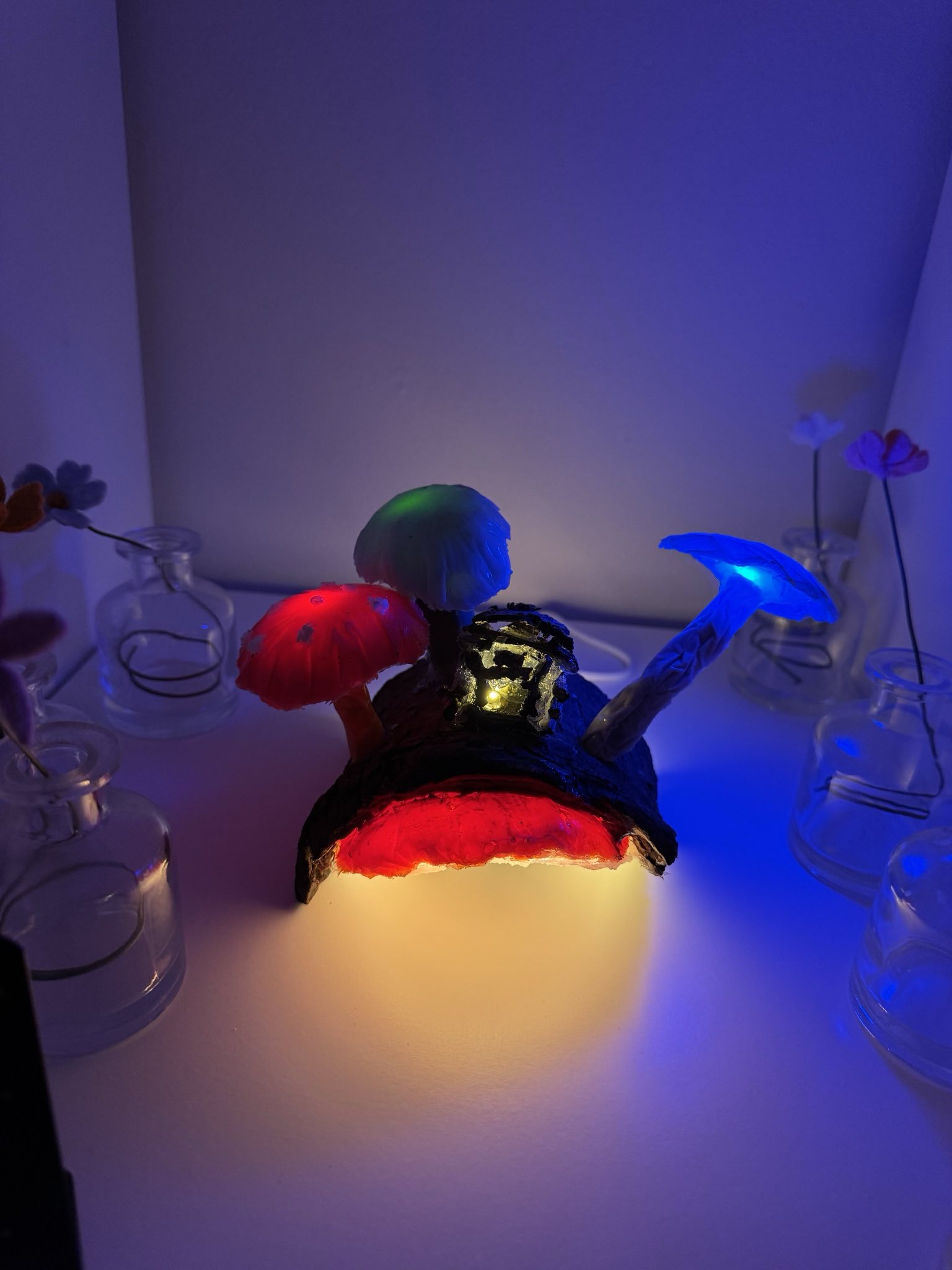
I glued the board in place, covered it with the bottom portion of the amanita – and just like that, the physical components of the lamp were done! I next got started making a real light pattern.
Code
Update: The below is outdated now, but is a fun look back at how I wrote my original script. The new controlling script is written in ESPhome via yaml, and performs all the same fundamental functions, except it’s no longer just a nightlight but is a dimmable light in HomeAssistant.
This was my first coding adventure with C++ – I’ll shamefully admit that I asked ChatGPT a lot of questions in order to get me started here, but after a while I started to realize it wasn’t that much more helpful than Googling my question and finding StackOverflow threads.
Prior to this little project, I haven’t done basically anything with hardware, and it took a lot of learning to understand how to use non-blocking timing patterns to make sure that the lights don’t interfere with each other – and so that the lamp is constantly probing the surrounding light levels.
In short, the loop function starts by checking the ambient light – if it’s too light out, the lamp goes into a light sleep mode and checks again a few times each second. If the ambient light is dim enough, it triggers a step in the pattern light function.
On boot, each LED is assigned the minimum brightness value, an empty timer, and a random time interval. Using the random time interval, each LED is then assigned a calculated timespan for updating its brightness level. Each time the pattern loop begins, it goes through each LED and assesses whether an appropriate amount of time has passed to either increase or decrease the brightness ([total interval] / [num steps between min and max brightness]) – and if an appropriate amount of time has passed, the LED steps up until it hits the max brightness and then goes down until the minimum brightness. At the minimum brightness, the LED is assigned a new time interval.
The goal was to make the mushrooms look like they’re breathing, and I like to think it’s pretty good!
The LED inside the cabin flickers to make it seem like a little dweller is sitting by the fire. This isn’t directly controlled by the ESP32 – I just stole the LED from an electric candle, so it has a semi-random flickering pattern built into its PCB. The unfortunate side-effect of this is that I cannot control the brightness myself to adjust its pattern, but that’s ok.
Future Improvements
- I truly did not plan for how difficult it would be to solder the lights to the board. In the future, I would vastly prefer to make the wires coming out of the LEDs much longer and tipped with 2-pin connectors so that they can just plug into the PCB! This would also help protect the lights from shorting to ground so easily…
- I got this done! It required ripping out the original board and making an entirely new one, but the final product is much more robust!
- This is an easy fix I just haven’t done yet, but this nightlight has a silly flickering behavior when the ambient light is just barely dark enough to trigger the lamp because the lamp itself provides enough light to turn itself off! This would be fixed by just having two brightness thresholds, the “off” threshold being brightness than the “on” threshold – that way it turns on in relatively dim light and turns off only when it’s substantially brighter. I’ll go back and fix this sometime!
- Also fixed, mostly by removing the nightlight behavior. I decided it would be fun to keep the LDR as a sensor entity in HomeAssistant, so I can “see” the day/night cycle of our living room – but it’s no longer toggling the lamp on and off.
- A slightly more complicated coding fix is to alter the brightness stepping function so that it better matches the perception of the human eye: right now it linearly adjusts the PWM value from min (25) to max (255) – but the eye perceives differences in brightness non-linearly. Someday I’ll go back and rewrite this so it’s more like the sine curve that we use to sense brightness.
- Fixed this too!
- I’m still working on the MQTT/HomeAssistant connection for this lamp – it’s kind of a shame to use the blazing fast ESP32 at about 1% of its capacity, and just wasting the wifi/bluetooth connections! I’ll update here when I’ve successfully incorporated different patterns that can be controlled within an HA dashboard.
- Done! I decided that different patterns aren’t interesting to me because I really like the breathing effect. The lamp is now controlled purely in HomeAssistant.